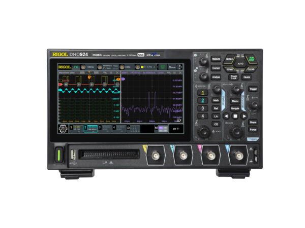
Rigol DHO924 – Mixed Signal Oscilloscope (4 Channels / 250 MHz)
$699.00
250MHz, 1.25GSa/s, 4 channels, 16 digital channels
Description
Rigol DHO924
4 analog channels / 250 MHz bandwidth
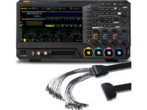
16 digital channels (requires optional PLA2216 logic probe)
This model does not have a 25 MHz arbitrary function generator
Small footprint: 10.5”W x 6.4”H x 3.1”D
7″ (1024×600) capacitive multi-touch screen
Mixed Signal Oscilloscope (4 Channels / 250 MHz)
The DHO900 series is RIGOL’s latest high-performance, economical digital oscilloscope. Though compact in design, it offers superior performance with a capture rate up to 1,000,000 wfms/s (in UltraAcquire Mode), 50 Mpts memory depth, 12 bits resolution, and low noise.
Rigol offers four versions of its DHO900 series, with analog bandwidth of 125 or 250 MHz, and the option for a 25MHz single channel arbitrary function generator and bode plot analysis.
Model Analog Ch. Analog BW Function gen. Bode plot
DHO914 4 125 MHz No No
DHO914S 4 125 MHz Yes Yes
DHO924 4 250 MHz No No
DHO924S 4 250 MHz Yes Yes
16 digital channels
The DHO900 series supports 16 digital channels. One instrument can make an analysis on both analog and digital signals to meet embedded design and test scenarios. With an affordable price equivalent to purchasing an entry-level instrument, you can access auto serial and parallel bus analysis, bode plot analysis, and other functions to meet testing demands in the R&D, education, and scientific research fields.
Please note, use of the digital channels requires the optional PLA2216 logic probe.
Arbitrary function generator (DHO914S and DHO924S only)
The DHO914S and DHO924S include a single channel, 25MHz arbitrary function generator. It features a sample rate of 156MSa/s, 14-bit vertical resolution, and outputs the following standard waveforms: sine, square, ramp, DC, noise, and also supports user-defined waveforms.
This integrates the signal source and the oscilloscope into one, providing great convenience for engineers who need to use the signal source and oscilloscope at the same time.
Bode plot (DHO914S and DHO924S only)
Bode plot is a way of graphically displaying the frequency response of a system. In the switch power supply and operational amplifier’s circuit feedback network, the Bode plot provides the curves displaying the variation of gain and phase with the frequency for a loop analysis. Through the analysis on the system’s gain and phase margins, you can determine the stability of the system.
With the built-in signal generator module, the DHO914S and DHO924S generate the sweep signal of a specified frequency range and outputs to the switch power supply circuit under test. Then, the oscilloscope draws a Bode plot displaying the variation of phase and gain with different frequencies.
Remote control
The DHO900 supports several methods of remote control:
User-defined programming
Program and control the instrument by using the SCPI (Standard Commands for Programmable Instruments) commands
PC software
Use PC software to send commands to control the instrument remotely. RIGOL Ultra Sigma is recommended. Software is available for download from the Rigol website
Web control
Connect the instrument to the network, input the IP address of the instrument into the address bar of the browser of your computer and the web control interface is displayed
View the display of the real-time interface of the instrument
Touch screen gestures
The instrument’s large capacitive touch screen makes operation and configuration easy. Actions supported by the touch screen controls include tapping, pinching and stretching, as well as dragging.
Tap
Use one finger to tap the symbol or characters on the screen to perform a variety of functions including selection, navigation and more
Drag
Use one finger to select the object, and then drag the to a new location
Pinch and stretch
Pinch or stretch two points on the screen with two fingers to zoom in or out
Pinching and stretching horizontally can adjust the horizontal time base of the waveform
Pinching and stretching vertically can adjust the vertical scale of the waveform
User interface overview
1. Waveform view 8. Result sidebar
2. Run state 9. Split screen display
3. Horizontal timebase 10. Notification area
4. Sample rate and memory depth 11. Math
5. Horizontal position 12. Function generator (DHO914S/DHO924S only)
6. Trigger 13. Channels
7. Function toolbar 14. Function navigation icon
Front panel overview
1. 7” touch screen 9. Trigger controls
2. Multipurpose knobs 10. Horizontal controls
3. Analyze key 11. Vertical controls
4. Measure key 12. Probe compensation signal output / ground terminal
5. Cursor key 13. Analog channel inputs
6. Common tool keys 14. Digital channel input
7. Touch lock keys 15. USB host
8. Quick action key (self defined) 16. Power key
Rear panel overview
1. AUX out 6. USB-C power connector
2. AFG out (DHO914S/DHO924S only) 7. Security lock hole
3. LAN 8. Ground terminal
4. USB device 9. Mounting screws (VESA 100×100)
5. HDMI


Reviews
There are no reviews yet.